- Home
- Products
- Brushless Motor
- Brushless Motor(DC input)
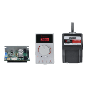
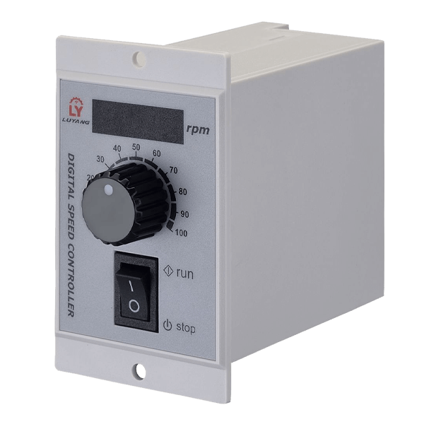
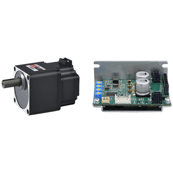
- 100W Brushless Motor Driver
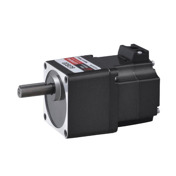
- Output power: 100W.
- Standard reduction ratio: 5~100 ratio.
- Power input voltage: DC24V
- Speed control range: 100~3000rpm/min.
- Protection functions: overload, overcurrent, overspeed, motor rotation, detector abnormality and other protections.
Specifications
| Motor model | Round shaft type | 9BH100A-K25 | |||||||
|---|---|---|---|---|---|---|---|---|---|
| Pinion type | 9BH100GB-K25 | ||||||||
| Driver model | BHD100-K | ||||||||
| Rated output | (W) | 100 | |||||||
| Power input | Rated voltage | (V) | DC24 | ||||||
| Voltage tolerance | -15% ~ +15% | ||||||||
| Rated input current A | (A) | 6.0 | |||||||
| Maximum input current A | (A) | 9.8 | |||||||
| Rated RPM | (r/min) | 2500 | |||||||
| Speed control range | (r/min) | 100~3000 | |||||||
| Speed change rate | - 0.5% ~ +0.5% | ||||||||
| Rated torque | (N-m) | 0.38 | |||||||
| Maximum torque | (N-m) | 0.58 | |||||||
| Rate Time | Continuous | ||||||||
| Degree of Protection | Motor: IP40 Driver: IP00 | ||||||||
| Insulation class | Class B | ||||||||
| Shaft material | Motor shaft, reducer output shaft: steel | ||||||||
| Driver detector | Hall element | ||||||||
| Insulation current protection | Motor: Coil to case DC500V 100MΩ or more Driver: Power terminal to driver heat sink DC500V 100MΩ or more |
||||||||
| Insulation pressure resistance | Motor: coil to housing AC1500V/1 minute Driver: Power terminal to driver shell AC500V/1 minute |
||||||||
| Usage environment | Temperature: 0 ~ +40℃ (no freezing) Humidity: below 85% (no condensation) Altitude: below 1000m above sea level Environment: No corrosive gas or dust. Do not use in explosive, radioactive places, magnetic fields, vacuum and other special environments. |
||||||||
| Storage environment | Temperature: -20 ~ +70℃ (no freezing) Humidity: below 85% (no condensation) Altitude: below 3000m above sea level Environment: Avoid direct sunlight, less salt and well-ventilated place. |
||||||||
Product model list
| Motor model | Type | Frame number | Output power | Motor shaft type | Driver model | Power supply voltage | Corresponding gearbox | Reduction ratio |
|---|---|---|---|---|---|---|---|---|
| 9BH100A-K25 | Brushless motor | 90mm | 100W | Round shaft | BHD100-K | DC24V | - | - |
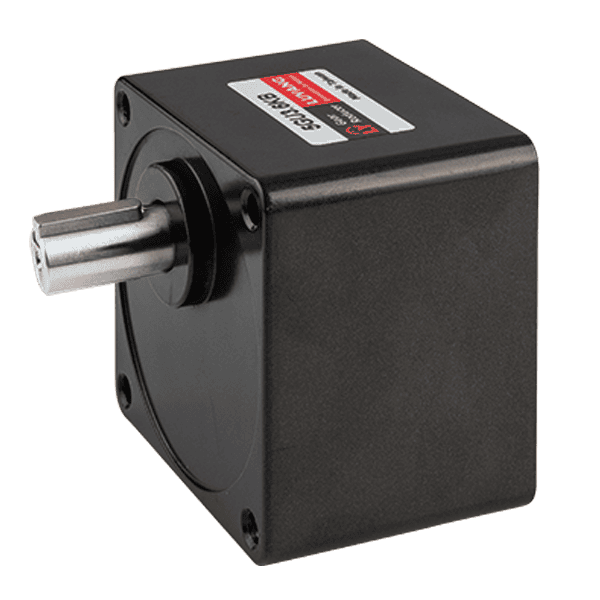
| 9BH100GB-K25 | Brushless motor | 90mm | 100W | Helical gear shaft | 9GB | 5,10,15,20,30,50,100 |
Motor torque characteristics
Reducer specifications
| Reducer | Deceleration ratio | 5 | 10 | 15 | 20 | 30 | 50 | 100 | ||
|---|---|---|---|---|---|---|---|---|---|---|
| Motor shaft speed | ||||||||||
| Output shaft speed | (r/min) | 2500r/min | 500 | 250 | 167 | 125 | 83 | 50 | 25 | |
| Allowable torque | (N.m) | 100W | 100~2500r/min | 1.75 | 3.49 | 5.24 | 6.98 | 9.99 | 16.68 | 30.00 |
| 3000r/min | 0.87 | 1.75 | 2.62 | 3.49 | 5.04 | 8.34 | 16.68 | |||
| Allowable hoisting load | (N) | 100W | Distance from the front of the output shaft 10mm | 300 | 400 | 500 | ||||
| 100W | Distance from the front of the output shaft 20mm | 400 | 500 | 650 | ||||||
| Allowable thrust load | (N) | 100W | 150 | |||||||
| Operation direction | In the same direction as the motor | In the opposite direction of the motor | ||||||||
External View
Unit:mm
| Ratio | L |
|---|---|
| 5~20 | 96mm |
| 30~100 | 109mm |

Operation Instructions
■ Driver Functions

■ Functions
| Functions | Content | ||
|---|---|---|---|
| Speed setting method | Via SP1 internal speed setter (VR1) | ||
| Via SP2 external speed setter | |||
| External DC voltage via SP2: DC 0~5V 1mA or more | |||
| Torque range | Adjust and set the torque range through the torque setter (VR2). | ||
| Acceleration time, deceleration time* | Set within the range of 0.1~12 seconds | ||
| Settings can be made using the acceleration time setter (VR3) and deceleration time setter (VR4). | |||
| *The actual acceleration time and deceleration time are affected by the customer's usage conditions, load inertia and load torque, etc. | |||
| Input signal | START/STOP input, RUN/BRAKE input, switching of running direction, selection of internal or external speed setting, setting of torque range, input of ALARM-RESET. | ||
| Regenerative resistor | Connectable pick-up resistor connector (P4) | ||
| Output signal | SPEED output, ALARM output | ||
| Protection function | Overload, motor detector abnormality, overvoltage, undervoltage, overspeed, motor stall, driver abnormality, initial start abnormality. | ||
Note: Please refer to the BU series operation manual for relevant details.

