


")
")


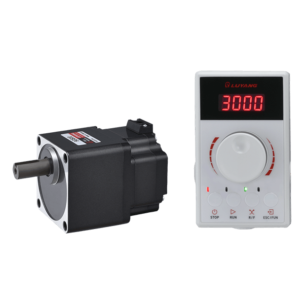

- Output power: 120W
- Standard reduction ratio: 5~100 ratio.
- Power input voltage: single-phase AC100~120V, single-phase AC200~240V, three-phase AC200~240V
- Speed control range: 80~4500rpm/min.
- Protection functions: overload, overcurrent, overspeed, motor rotation, detector abnormality and other protections.
Specifications
| Motor model | Round shaft type | 9BU120A-A30 | ||||||||
|---|---|---|---|---|---|---|---|---|---|---|
| Pinion type | 9BU120GB-A30 | |||||||||
| Driver model | BUD120-A | BUD120-C | ||||||||
| Rated output | (W) | 120 | ||||||||
| Power input | Rated voltage | (V) | Single phase 110V | Single phase 220V/ Three phase 220V | ||||||
| Voltage tolerance | -15% ~ +15% | |||||||||
| Frequency | (Hz) | 50/60 | ||||||||
| Frequency allowable error | - 5% ~ +5% | |||||||||
| Rated input current A | (A) | 2.33 | 1.41/ 0.81 | |||||||
| Maximum input current A | (A) | 6.8 | 4.1/ 2.0 | |||||||
| Rated RPM | (r/min) | 3000 | ||||||||
| Speed control range | (r/min) | 80~4500 | ||||||||
| Speed change rate | - 0.2% ~ +0.2% | |||||||||
| Rated torque | (N-m) | 0.38 | ||||||||
| Maximum torque | (N-m) | 0.57 | ||||||||
| Rate Time | Continuous | |||||||||
| Degree of Protection | Motor: IP40 Driver: IP20 | |||||||||
| Insulation class | Class B | |||||||||
| Shaft material | Motor shaft, reducer output shaft: steel | |||||||||
| Driver detector | Hall element | |||||||||
| Insulation current protection | Motor: Coil to case DC500V 100MΩ or more Driver: Power terminal to driver heat sink DC500V 100MΩ or more |
|||||||||
| Insulation pressure resistance | Motor: coil to housing AC1500V/1 minute Driver: Power terminal to driver shell AC500V/1 minute |
|||||||||
| Usage environment | Temperature: 0 ~ +40℃ (no freezing) Humidity: below 85% (no condensation) Altitude: below 1000m above sea level Environment: No corrosive gas or dust. Do not use in explosive, radioactive places, magnetic fields, vacuum and other special environments. |
|||||||||
| Storage environment | Temperature: -20 ~ +70℃ (no freezing) Humidity: below 85% (no condensation) Altitude: below 3000m above sea level Environment: Avoid direct sunlight, less salt and well-ventilated place. |
|||||||||
Product model list
| Motor model | Type | Frame number | Output power | Motor shaft type | Driver model | Power supply voltage | Corresponding gearbox | Reduction ratio |
|---|---|---|---|---|---|---|---|---|
| 9BU120A-A30 | Brushless motor | 90mm | 120W | Round shaft | BUD120-A | Single phaseAC100~120V | - | - |
| BUD120-C | Single phaseAC200~240V/ Three-phaseAC200~240V | |||||||
| 9BU120GB-A30 | Brushless motor | 90mm | 120W | Helical gear shaft | BUD120-A | Single-phaseAC100~120V | 9GB | 5,10,15,20,30,50,100 |
| BUD120-C | Single-phaseAC200~240V/ Three-phaseAC200~240V |
Motor torque characteristics

Reducer specifications
| Reducer | Deceleration ratio | 5 | 10 | 15 | 20 | 30 | 50 | 100 | ||
|---|---|---|---|---|---|---|---|---|---|---|
| Motor shaft speed | ||||||||||
| Output shaft speed | (r/min) | 3000r/min | 600 | 300 | 200 | 150 | 100 | 60 | 30 | |
| Allowable torque | (N.m) | 120W | 80~3000r/min | 1.65 | 3.30 | 5.04 | 6.69 | 9.60 | 15.91 | 30.00 |
| 4500r/min | 1.17 | 2.34 | 3.51 | 4.68 | 6.66 | 11.07 | 22.23 | |||
| Allowable hoisting load | (N) | 120W | Distance from the front of the output shaft 10mm | 300 | 400 | 500 | ||||
| 120W | Distance from the front of the output shaft 20mm | 400 | 500 | 650 | ||||||
| Allowable thrust load | (N) | 120W | 150 | |||||||
| Operation direction | In the same direction as the motor | In the opposite direction of the motor | ||||||||
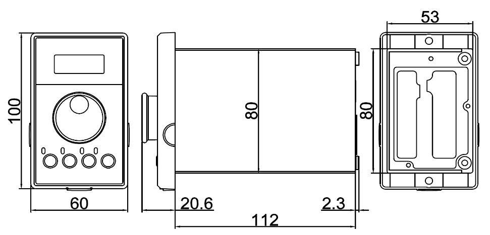
External View


Unit:mm
| Ratio | L |
|---|---|
| 5~20 | 96mm |
| 30~100 | 109mm |
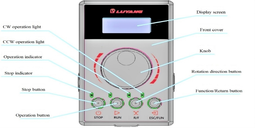
Operation Instructions
■ Driver Functions
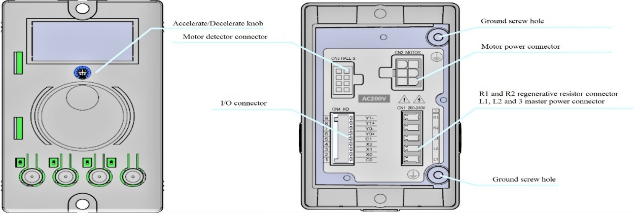
- Main power connector
- Single-phase input: Please connect L1 and L2 to the main power connector.
- Three-phase input: Please connect L1, L2, L3 to the main power connector.
■ Functions
| Functions | content | |
|---|---|---|
| Operation Mode | Motor start/stop | |
| Switch running direction | ||
| Adjusting speed | ||
| Selection of three operating modes | ||
| Four-stage operating setting (speed, torque limit, acceleration/deceleration time) | ||
| Upper and lower limit settings of motor speed | ||
| Set and display the speed reduction ratio or increase ratio | ||
| Gentle start/soft stop | ||
| Simple stop and hold mode | ||
| Speed setting method | Use the knob to adjust the speed | |
| Use I/O to set the speed of four-stage running data | ||
| Acceleration time, deceleration time* |
Analog Setting: Set by acceleration and deceleration knob. Set within the range of 0.2~15 seconds. | |
| Digital Setting: Set the number of each segment of the operating data. Set within the range of 0.2~15 seconds. | ||
| *1 Actual acceleration time and deceleration time are affected by the customer's usage conditions, load inertia, load torque, etc. | ||
| Input signal | Optocoupler input method: power supply must be less than 10mA | |
| Operation using internal power supply: DC5V | ||
| Connectable external DC power supply: DC5~30V | ||
| SINK input/SOURCE input | ||
| Three groups of inputs (X0~X2) can be assigned to signals. Factory settings: [FWD], [REV], [M0] | ||
| Output signal | Optocoupler, transistor open collector circuit output | |
| External DC power supply: DC5~30V | ||
| SINK output/SOURCE output | ||
| Two sets of outputs (Y0~Y1) can be assigned to the signal. Factory setting: [SPEED OUT], [ALARM OUT] | ||
| Protection function | Abnormal alarm display, overload, overcurrent, overvoltage, undervoltage, overspeed, motor stall, detector abnormality, safe start, driver overtemperature, driver power module abnormality. | |
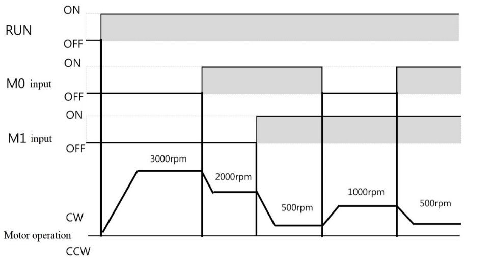
■ Multi-stage speed operation
While using multi-stage speed, switch between M0, M1 and input to perform multi-stage operation.
Example:
| Operation data | M0 | M1 | Speed |
|---|---|---|---|
| No.1 | OFF | OFF | 3000 |
| No.2 | ON | OFF | 2000 |
| No.3 | OFF | ON | 1000 |
| No.4 | ON | ON | 500 |
Note: Please refer to the BU series operation manual for relevant details.


